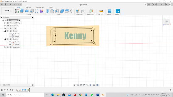
Part 1:Name tag
1.
The first step to make a name tag is to create a
sketch.
2.
Next is to select and form a rectangle of 65mm
by 25mm.
3. Follow by offsetting the side of rectangle by
2mm.
4.
To remove the sharp corners, select fillet with
a radius of 5mm.
5.
Next, create a line with a 7mm distance away
from the left width of rectangle.
6.
After the line is created, add a point at the middle
of the line and draw a circle with radius 5mm.
7.
Select create text, type name and select impact
as the front type then adjust the height to fit the rectangle. Click finish
sketch when it is completed.
8.
Extrude the base 3mm without the hole to make
the sketch 3D.
9.
Now select the border and name to extrude 1.5mm.
10.
Lastly, offset the plane by 3mm.
11.
Finish
Reflection
After this week's lesson, we were task to design a name tag using Computer aided design(CAD) Fusion 360 as a form of recap as this is what we have learnt from the previous module CP5065. To help us to recap from what we have learnt from the previous module, we task to follow steps from the YouTube videos when we were designing our name tag. To help us to remember what we had did, our lecturer want us to document by taking screenshot on every steps we made while making our own name tag so that we can refer back just in case we have forgotten what to do.
This experiment is important as it help us to recap on what we have learnt earlier on. Also, as computer aided deign is an important skill that we can use while deigning or product or prototype. By picking up this skill, it can save a lot of time in prototype making as we don't have to make every single parts of the prototype by ours which can be extremely time consuming when the prototype have a lot of parts. This task was interesting as we are able to come out with name tags with unique design.
I used to think that I am bad at using fusion 360 from the previous module as experience as I required a lot of help from my lecturer and friends. Now I think that I am more competent in using fusion 360 as through this recap, I realised that I am better at using fusion 360 and I do not required much help from others. So that next time I will try to use fusion 360 to make my prototype whenever it is possible as it save a lot of trouble and time.
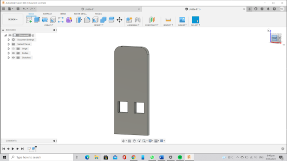
Part 2: Handphone standNext, I am task to design a handphone stand using parametric construction in which this design need to be able to be laser cut.
1)Firstly, I start constructing the base of the phone Holder by listing out the dimensions of the base.
2)Next, I uses the line function to form out the shape I want and inputting the dimensions as what stated in point 1.
3)After forming the shape that I need, I select the trim function to trim away the unwanted parts from the design.
4) Lastly, I select finish sketch and extrude the design to make it 3D. When extruding, select symmetry and select thickness from point 1.
5) After the base is completed, start making the body of handphone stand by stating the dimensions of the handphone stand and form the shapes of handphone stand.( similar steps use to make the base)
6) Next, to prevent injuries cause by the sharp edges of handphone stand, we can remove the sharp edges by selecting the fillet and the radius we need to remove the sharp edges.
7) Lastly, to finish up the body of handphone stand, select finish sketch and extrude the handphone stand to the same same thickness as the base to ensure that the base can be fit into the body.
Reflection
After the we had learnt about parametric construction, we we task to design a phone holder using parametric construction. At first, I did not understand how to apply parametric construction and wanted to design a simple one just for the sake of submitting the work. However, the design that I had came up with cannot be laser cut and hence I need to redesign. When I was redesigning, I had a better understand of parametric construction and I manage to came up with a new design that can be laser cut. Although the design I came up with is simple but through this experience, I have a better understanding of parametric construction and knowing how to apply it while designing a product.
This task is important as it allow our lecturer to assess on how competent we are to apply what is taught in the lesson. I feel that only by doing it we then can master the skill. Also, parametric construction is an important skill as it allow us to make modify to our design with having the need to redo the whole thing and hence, it helps us to save time for other important things. This task is interesting as I discovered a new way to modify my design without redoing the whole thing which I find it very useful for the future practical.
I used to think that parametric construction is very difficult to apply as at first I do not understand what is being demonstrate in the videos. Now I have understand what is being taught in the videos and I am able to come out with a parametric design without the help from others. So next time whenever is possible, I will try try to apply parametric construction as even there's a need to make changes, I can done it easily.


Comments
Post a Comment