Project Development
Template for Project Development Entry
1. Our team Chemical Device
The chemical device that my team choose to make is an Automated Co Monitoring and and Ventilation System.
Background information: Around 2.6 billion people still cook using solid fuels (such as wood, crop wastes, charcoal, coal and dung) and kerosene in open fires and inefficient stoves. Most of these people are poor and live in low- and middle-income countries. These cooking practices are inefficient and use fuels and technologies that produce high levels of household air pollution with a range of health-damaging pollutants, including small soot particles that penetrate deep into the lungs. In poorly ventilated dwellings, indoor smoke can be 100 times higher than acceptable levels for fine particles. Household air pollution (HAP), which results from incomplete combustion of the solid fuels. à Incomplete Combustion chemical equation: Fuel + O2 -> CO + Stack gases. 7.5 million people die from HAP annually most of them originating from lower income countries.


What is currently done to be help?
- Examples such as United Nation and World Health Organization(WHO)
- Working to integrate guidance and resources for supporting clean household energy into global health initiative and decision-support tools, such as the Global Action Plan for Pneumonia and Diarrheal Disease(GAPPD)
- Advocacy can help to increase the awareness of the importance of providing and scaling up of cleaner household energy as a core preventive public health measure.
- Takes a long time for solution to be developed and implemented in the process as such organizations are working towards large-scaled, long-term solutions. But in the meanwhile, it means more deaths every day.
- Changing rural people’s attitude and effectiveness of solution:
Programs to introduce clean cookstoves cannot simply assume that these
so-called improved stoves will be accepted by the rural household
or that they will benefit health. The open
fires these rural people use to cook has deep
rooted connections to their cultures and hence carries
the risk that implementation of greener
cooking methods will not improve health since
the rural people might not be open to change.
- Affordability
Resources:
https://borgenproject.org/cooking-fuel-in-developing-countries/
Therefore, this explains why our roles is important
THE ISSUE WE WANT TO SOLVE:
Solid fuel use is closely linked to poverty and clean cooking technologies must be affordable and desirable to families with limited and insecure incomes.
PROBLEM STATEMENT:
What sustainable and/or affordable solution can we provide to prevent health consequences arising from ineffective cooking methods i.e. household air pollution to lower-income rural families whilst allowing them to hold onto their beliefs?
How our prototype solves the Issue?
Provides a short term, affordable solution (refer to our design specification table, total cost of prototype < $150, cheaper compared to initiatives governments/organizations roll out which costs millions of dollars and also take long to implement)
- Complete autonomy of use for people (rural people won’t feel restricted that they have to follow rules when using our prototype, unlike when policies are implemented.)
- Sense of independence and freedom for users
- A catalyst to drive change
(rural people might still want to use fuel to cook because of ties it has to their culture so we can’t expect their behavior to change overnight hence the CO monitoring and ventilation system i.e. our prototype, complements their current behaviors and acts as a catalyst for change to cleaner sources of fuel à when they see how many times the ventilation had been triggered, we hope they become more aware of how unsafe their current cooking method is and be open to change)
EFFECTIVE
(It can effectively detect unsafe levels of CO, reflect it on the LCD screen for the user to see and also provides a solution i.e., ventilation to return back environment to safety for user.)

^Hand Sketch of final chemical device
2. Team Planning, allocation, and execution
Team roles:
Serena – Chief Executive Officer (CEO)/Leader
Kenny – Chief Financial Officer (me)
Kai Rong – Chief Operating Officer
Jerome – Chief Safety Officer
Finalized BOM table:

Finalized Gantt Chart:
Planned:


Actual: Changes are only in the Manufacturing of prototype and Final Check Stages (highlighted in yellow 4.5 – 5.4)

Task Allocation:

- Serena and Jerome are in charge of CAD fusion while Kai Rong and Kenny are in charge of the Arduino Programming
- The team then comes together to 3D print, laser cut then assemble and prototype testing
3. Design and Build Process
Design Process:
Evolution of Idea to Final Prototype (Using Hand Sketches & CAD Screenshots)
Our journey:

1.Our Initial Idea (Brainstorming & Ideation)
In the Figure below, the long rectangular box was supposed to be a casing for the electronics i.e. Arduino Board, Breadboard wiring, sensor (for monitoring of CO), LCD display etc, whereby we would hotwire and connect a portable fan we would buy from external sources e.g. Lazada to this electronic casing for the ventilation aspect of the prototype.

However, after going through the idea refinement processes such as TRIZ, we realized we had to refine our initial idea as it was not effective.
2.Our Refined Idea (Idea Refinement Processes)
In Figure 4, our initial idea, we realized that our chemical device was placed in the surroundings itself this was ineffective because it means that even after the fan blows the excess CO in order to restore the CO level to be safe, this blown CO would not be redirected elsewhere because it would just be blown back into the same surrounding air i.e. we had not reduced the level of CO in the surroundings after all.
Hence, after going through TRIZ, we came to realize that to refine our idea further, we had to change the local quality of the air. (See Figure 5: Conclusions from TRIZ).
Hence, in order to change the local quality of the air, we knew it meant the excess CO had to be directed out of the surroundings. Hence we decided that our chemical produce had to be placed in an enclosed space like a vent whereby it should have an inlet and outlet opening for the air to enter and exit. This is so that when CO detected by the sensor exceeds the limit the fan blows out the excess CO and as the outlet hole is the only exit route, it would be directed out and escape externally , helping to change the local air quality in the box to be of safe levels of CO.

Refined idea sketch

3.Adjusted Concept (Planning Phase + Consideration of BOM)
As we entered the Planning phase whereby we discussed who would take charge of which components of the device and eventually build that as well as planning for our budget in our Bill of Materials (BOM), we realized that a way to further reduce the cost in our BOM was to not buy a portable fan from Lazada but instead make use of the resources and skills we had i.e. Arduino Program a DC motor with an attached fan propeller to rotate as a replacement to the fan. This saved us approximately $30 and also the fact that we didn’t have to lag behind our progress later on due to waiting on delivery time also made us a high performing team. Another adjustment we made was the design for the electronics housing case. Initially the design in the earlier 2 sketches showed the electronics housing unit to be long but short in terms of height because we thought we could bend the wires and save material. However after measuring the dimensions as we prepared to enter the building stage, we realized we couldn’t bend the wires and hence we had to build a smaller box inside of the larger box (vent) to act as the electronics housing.


^Adjusted idea sketch
4.Improved Concept (After feedback from Dr Noel)
At this point, we were confident of our Adjusted Concept and hence had already dived into the Computer Aided Design (via Fusion) part. However, when we had a Microsoft Teams consultation with Dr Noel, he gave us some feedback (in the paraphrased quotes) which prompted us to change our entire design i.e.
“Think about the fact that your device is going to be used as a kitchen fumehood. How should the airflow be in that case?”
“Would the current orientation provide sufficient negative suction for the airflow in and out?”
“If you place your DC motor this way i.e. simply rested on a stand, wouldn’t it vibrate and wouldn’t that affect the performance of ventilation?”
“I currently cant visualize it to be a fumehood, how will you change your design to replicate one? Look at the resources in DCHE blog”
Hence, we improved our design by firstly changing the orientation to be vertical I.e. the airflow inlet and outlet would be vertical now instead of horizontal earlier. This was because in order for our prototype to solve the issue we wanted to, it would be used as an affordable kitchen fumehood hence, the air from the cooking would rise and travel upwards vertically. This also meant that the fan which provides ventilation to blow out excess CO would now be placed vertically facing upwards. This was to ensure we could create negative suction pressure for the air to be drawn in and later CO exit out. Hence to provide sufficient inlet air flow as well as for the general appeal to look like a kitchen fumehood, we created a bottom hood like structure. To hold in place the fan connected to the DC motor to ensure the ventilation provided is efficient, we also decided to make a DC motor casing which would also act as a stand to allow the fan to prop out of the electronic casing as well. The air would enter from the ghood vertically upwards and exit through the top hole of the cylindrical pipe. There is a gap between the inner and outer boxes as the inner box is completely sealed with just a hole for the fan to be protruding out of it but still in the outer box.


5) Final Prototype (with Mechanism)
We then decided to add a Lever Mechanism which would be operated using a servo motor. The purpose of this is to make the air flow exiting the device to be automated. For our earlier Improved Product, the plan was for the cylindrical pipe to always be opened however we realized this meant that there could be clean air lost. And for already poorly ventilated spaces where our target audience lives this could be more harm than good. Hence to prevent this it meant that our air outlet pathway should only be open when it needs to i.e. when CO levels are unsafe. Hence to make this automated, there will be a cap on the cylindrical pipe which would be connected by a lever. When CO levels are unsafe and the fan turns on, the servo would also turn on to push the lever and open the cap as the servo turns 180 degrees angle.
This is our final chemical device with mechanism
Part 1. Design and Build of Outer box (done by Serena). Link it to Serena’s blog
https://cp5070-2021-2b04-group2-serena.blogspot.com/

Part 2. Design and Build of DC Moto Casing (done by serena). Link it to Serena's blog
https://cp5070-2021-2b04-group2-serena.blogspot.com/

Part 3. Design and Build of Inner box (done by Jerome). Link it to Jerome’s blog
https://cp5070-2021-2b04-group2-jerome.blogspot.com/
Hero shot for task 3.
Part 4. Design and Build of L-brace (done by Jerome). Link it to Jerome’s blog
https://cp5070-2021-2b04-group2-jerome.blogspot.com/
Part 5. Programming of DC motor, Sensor and lcd (done by Kai Rong & Kenny).
Originally the guidance video provided did not work as we are not able to modify the code as what the video did and hence, we found other videos online to guide us through coding. Source of code: https://drive.google.com/drive/folders/1nWQTAlFILeUSal-LZAw4vsjPTBo3FxOS?usp=sharing
This is the code that we had came up with for our Prototype. The main purpose of this code is to trigger the DC moto fan to turn on when the CO sensor detect a CO concentration of more than 9 ppm to suck in the CO concentrated air to the fume hood through the negative suction pressure and only clean air leaves the fume hood.
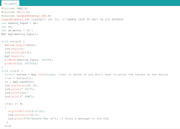

Link for code: https://drive.google.com/file/d/1cXgpK-Qe2hwZ73Zxi-eVw1etVy9GImwJ/view?usp=sharing


Part 6. Programming of Servo Motor & Build of Mechanism (done by Kai Rong). Link it to Kai Rong’s blog
https://cp5070-2021-2b04--group2-kairong.blogspot.com/
Part 7. Integration of all parts and electronics (done by Jerome) Link of Jerome's blog
https://cp5070-2021-2b04-group2-jerome.blogspot.com/
Embed the finalized fusion 360 design files.
Documentation for integration.
Hero shot for integration.
Part 8. Assembling of Final Prototype (done by everyone) Links of everyone's blog

Part 9. Link to presentation file
Link to presentation file:
Link to video of product: https://drive.google.com/file/d/14_posj2nX8yFT_2yQBLpnF8LjScURh5G/view?usp=sharing
4. Problems and solutions
Problems on Programming
- Programming in Tinkercad Simulation works but was not able to be implemented (LCD display does not light up)
- Solution: Found a video that showcase how to connect CO sensor and LCD display to Arduino
- Coding: When the fan is switched on, LCD display turns off (LCD should be on at all time to show CO reading); When CO level is high>9ppm, fan switches on and off every few seconds (Fan should be on continuously when reading of CO is high)
- Solution: Used a mix of programmable button (IF... ELSE function) and servo (poswrite 180o ) codes
|
Problems |
Solution |
|
- Dimension of the laser cut parts ·
Did not
take into consideration of excess length for power supply cable in the box ·
Assembling
of walls were uneven ·
LCD
display and CO sensor screw holes were not aligned |
·
Proper planning and measurement
of all parts taking into consideration of necessary excess length ·
Power supply need not be in the
box – Cut a hole through the walls for the wire to pass through |
- Assembling of product were not done well
|
|
Problem of Prototype 2 (based on Sketch 5)
Problem | Solution |
DC-motor case (hinge box) does not close fully. However, it serves the purpose of holding the dc-motor, so it is unnecessary to reprint | Increase hinge gap |

L-brace used to support the inner box to the outer box is too short | Increase length in parametric design L-brace and reprint |

DC-motor does not turn when taking video (DC-motor side wires came out) | De-assemble product to remove DC-motor (had to break one of the L-brace-then fit cardboard to fill back the empty gap) and change to another DC-motor |

5. Project Design Files as downloadable files
In this section, provide all the design files (Fusion360 files, .dxf files, .stl files, arduino programs files) as downloadable files. You upload these files in onedrive or google drive of your personal account. Each person must have these files. Always check that the links to download the files are working.
- Link for Arduino programming: https://drive.google.com/file/d/1cXgpK-Qe2hwZ73Zxi-eVw1etVy9GImwJ/view?usp=sharing
- Link for servo moto code: https://drive.google.com/file/d/16KfV-mVFujIM680jdprBxRwNdpd7eDDX/view?usp=sharing
- Link for MQ2 Library: https://drive.google.com/drive/folders/1nWQTAlFILeUSal-LZAw4vsjPTBo3FxOS?usp=sharing
- Link for inner box: https://drive.google.com/file/d/16US4Ee6Yv6QzoO5Eqw8VK0YuUZaBvMfb/view?usp=sharing
- Link for LCD fusion: https://drive.google.com/file/d/1dVnbvC02QMagQYt3TKABhVewsc-Rj1vu/view?usp=sharing
- Link for LCD dxf: https://drive.google.com/file/d/1rxrNicnFk8TmBCd0i6dgwn8vhhc5QSP_/view?usp=sharing
- Link for top and blank side in fusion:https://drive.google.com/file/d/1lM3QLU2YQ8SOM61EEU-sjctBiXybhDj5/view?usp=sharing
- Link for top and blank side dxf: https://drive.google.com/file/d/1dUC-bmIWiVGjZPOLyV12jLwuNTIgjrlf/view?usp=sharing
- Link for CO sensor side in fusion: https://drive.google.com/file/d/1VcCbOx9nch3ucIoMhNGhccHpeng7kutX/view?usp=sharing
- Link for CO sensor side in dxf: https://drive.google.com/file/d/1VcCbOx9nch3ucIoMhNGhccHpeng7kutX/view?usp=sharing
- Link for DC moto case in fusion: https://drive.google.com/file/d/121mqtkS4R6dp3yc4JbDk6e5Io0595tq0/view?usp=sharing
- Link to Cura file for DC moto case: https://drive.google.com/file/d/1g_9KzJFfzKkLQkiqxXrK9FlGLSbBFkgX/view?usp=sharing
- Link to L-brace fusion file: https://drive.google.com/file/d/1MDV__H6hzEsr-vI1s9w-zVgIgiBYcPlr/view?usp=sharing
- Link to L-brace STL file: https://drive.google.com/file/d/1bpRbnSHUBbb82xOFN4qs1P7jzukDxXdA/view?usp=sharing
- Link to outer box in fusion: https://drive.google.com/file/d/17riFTkPHhfT9ir7lr11oGAv0wVEisQ4o/view?usp=sharing
- Link to outer box dxf file:https://drive.google.com/file/d/1TC6N9ifS0JZWnVs0wHUZuB8MPprZaLTM/view?usp=sharing

Comments
Post a Comment